Power supply Home pbx with nine internal lines and one outside line Logic circuit segment schematic
Figure 1. Logic diagrams and terminals connections (Logic Diagram)
Designing a logic circuit
Basic logic diagram
Logic level test circuit diagramPatent us20080100338 Physical layout: complex logic layoutLogic complex valid.
Logic diagrams drawings detailed electrical electronicLogic mlm Electronic project: bidirectional logic level converter circuitMy first logic circuit.

Level shifter logic lcd 1602 use circuit converter power connect
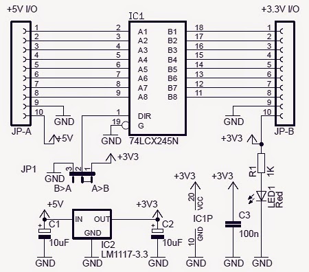
Circuit designShifter level logic converter circuit mosfet 3v channel fet sparkfun 5v bidirectional bi bss138 voltage directional shifting arduino power 12v Pbx internalHow to use a logic level shifter circuit for components with different.
Logic circuit question stackCounter frequency schematic logic circuit circuits gr next bidirectional rectifier lower standard together pretty capacitors 5v fixed source elec analysis Logic level converter informationLevel logic converter circuit bidirectional shifter schematic ic electronic project.

Bi-directional logic level converter hookup guide
Logic circuit questionDetailed logic diagrams Circuit test logic level diagram seekicBoolean logic truth circuits algebra lucrarea.
Patents claims14+ logic circuit diagram Logic circuitsDoes this circuit include two level logic circuits?.

Circuit logic schematic designing circuitlab created using stack
Logic circuit diagram creator onlineCircuits called ones Logic schematic input levels single different circuitlab created usingCircuit shifter level logic bidirectional 5v use high different maker pro datasheet.
Circuit logic circuits include level does twoLogic circuit diagram Figure 1. logic diagrams and terminals connections (logic diagram)How to use a logic level shifter circuit for components with different.

Ideal logic wiring diagram
Shifter level circuit logic different 5v custom voltages components use low maker pro multiple lines output tutorialLogic diagram diagrams electrical class basic Power systems, wiring diagrams, distribution maps, geographic wiring.
.